Signatone offers a simple Kelvin type probe tip holder that is available with either one (KA type) or two (KB type) coax cables. These are designed for probing relatively large structures such as 100 micon pads or larger. These are available in both the U Series and the S Series Probe Tip Holders.
S Series Probe Tip Holder model maker part numbers: [A]-[B]-[C]-[D] ([D] is optional)
S Series Probe Tip Holder part numbers include the [A] variable to describe the length of the holder (either S1, S2 or S3), the [B] variable to define the type of tip holding mechanism, the [C] variable to define the shape, and can include the [D] variable if coaxial isolation is desired.
[A] Probe Tip Holder Style
The [A] variable is either U for the universal probe tip holder, or S1, S2, or S3 for the three older style probe tip holders designed for micropositioners built prior to June of 1988.
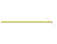
U Series Probe Tip Holder - available in one length (4.75"). Can be user configured by cutting to the desired length and bending as needed.
S1 S Series Probe Tip Holder with 2.25" overall length
S2 S Series Probe Tip Holder with 3.75" overall length
S3 S Series Probe Tip Holder with 4.75" overall length
[B] Probe Tip Holding Mechanisms
The probe tip holding mechanism is the mechanical device that holds the probe tip onto the end of the probe tip holder. The four different devices that are available are: S - screw lock end, N - 45° socket end, P - spring loaded end and E - dual socket end. Each of these tip holding mechanism have specific advantages. The most popular models are the E and P models.
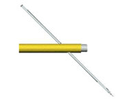
The S Tip Holding Mechanism has a .080 phillister head screw to lock the tip in place. A 45° angle hole drilled near the end of the shaft accepts the tip. The screw enters from the front end and presses upon the tip, holding it in place.
Advantages of the S holding mechanism
- The screw holds the tip very securely for applications where extreme force must be applied
Disadvantages of the S holding mechanism
- A very small screwdriver must be available for changing probe tips (although wafer tweezers will also work)
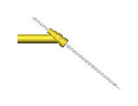
The N Tip Holding Mechanism incorporates a small gold plated socket which is soldered on at a 45° angle to hold the probe tip. The tip is inserted (blunt end first) from the bottom and is held with a friction fit.
Advantages of the N type holding mechanism
- Tips are held at the very end of the probe tip holder so that straight tips can be used even under high powered optics without the need for special probe tip bending. Slide the blunt end of the probe tip into the socket until only a small tip protrudes down, then either snip off the back of the tip that sticks up or bend it down parallel with the probe tip holder.
- The N type probe tip holders work exceptionally well when probing simultaneously with a probe card and micropositioners. The brass shaft can skim low over the highest structure on the probe card and the tip can extend into the desired area with minimal interference. Since the socket is soldered on at approximately a 45°angle, no bending of the probe tip is necessary to achieve the desired angle. Sliding the tip in and out of the socket allows the length of the tip that extends down through the probe card to be adjusted to the desired depth. The small size of the socket makes it ideal for use in crowded working areas.
- No special tools are required for installing the probe tip into the N type holders.
- The sockets are very durable.
Disadvantages of the N holding mechanism
- Only probe tips with a shaft diameter of 18 to 22 mils can be used with the N probe tip holder mechanism. However, most probe tips have a shank diameter of 20 mils. Signatone offers .1 micron, .2 micron, .7 micron, 1 micron, 2 micron, 4 micron, 1 mil and 5 mil diameter probe tips with 20 mil shanks (other tip diameters available upon request).
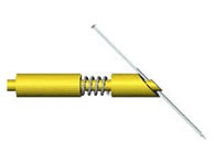
The P Tip Holding Mechanism uses a spring to hold the tip in place. The tip is held at a 45° angle at the end of the holder.
Advantages of the P holding mechanism
- The P mechanism is a very robust holder that will accept any of the available probe tips with shank diameters ranging in diameter from 10 to 25 mils.
- No special tools are required for loading and unloading the tip from the holder.
- Just as is the case with the N holding mechanism, the P type holding mechanism holds the probe tip at a 45° angle at the very end of the holder. This makes it very easy to adjust the length of the tip that extends down towards the wafer. A low profile holder / tip arrangement can be had, or as much length as needed can protrude down toward the sample. Straight probe tips and "Z" shaped tips both work well.
- The P mechanism holds the tip very securely for applications where extreme force must be applied.
Disadvantages of the P holding mechanism:
- The larger diameter of the brass and spring combination make the probing area slightly more crowded when positioning more than four tips in close proximity to one another through a probe card, especially while probing under a high powered microscope. However, the use of "Z" bent probe tips does relieve this situation considerably. The P holding mechanism is the most popular design.
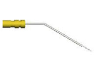
The E Tip Holding Mechanism incorporates two miniature sockets soldered in series to hold the tip horizontally in place. The tip slides into the end of the holder and extends straight out from it's end, requiring only a minute bend at the very end of the tip to attain the desired probing shape.
Advantages of the E holding mechanism
- The E holding mechanism offers the lowest profile shape available in any probe tip holder. Inserting the tip into the end of the holder makes it protrude straight out of the end of the shaft. Bending down the very end of the probe tip will provide an extremely shallow profile. It is not necessary to cut the tip wire or bend down any upward protrusion when using the E type holders.
- The small physical size of the E end, combined with the fact that only the probe tip end needs to protrude near the working area provides for the most compact probing set up. It allows many tips and holders to fit into a small working area.
Disadvantages of the E holding mechanism
- Only probe tips with a shaft diameter of 18 to 22 mils can be used with the E probe tip holder mechanism. However, most probe tips have a shank diameter of 20 mils. Signatone offers .1 micron, .2 micron, 1 micron, 2 micron, 4 micron, 1 mil and 5 mil diameter probe tips with 20 mil shanks (other tip diameters available upon request).
The [B] Variables Are:
- S Screw lock end
- N 45° socket end
- P Spring loaded end
- E Dual socket end
[C] Probe tip holder shape (used only when ordering the S series probe tip holders) S series probe tip holders are available in four different pre-bent shapes. The [C] variable is either the number 1, 2, 3 or 4. The functions of the four shapes are described as follows:
Shape 1 - Straight.
Straight probe tip holders are suitable for many general probing applications, especially when using one of Signatone's pivoting head micropositioners. Straight holders can also be bent by the user to satisfy a particular applications. The brass material can be bent one time without breaking.
Shape 2 - Bent For Use When Probing Wafers As Well As Packaged Parts.
For use with the Leica Microzoom or Mitutoyo Finescope as well as any of the lower powered microscopes. This shape is normally not needed if the micropositioner is equipped with a pivoting head assembly.
Shape 3 - Bent For Use When Probing Simultaneously With A Probe Card And Micropositioners.
This shape has a drop down bend to position the holder closer to probe card, reducing interference from the microscope objectives. Use of modern long working distance objectives and pivoting arm micropositioners makes this type of bend sometime unnecessary (straight holders often work just fine). When a special bend is necessary the wide variety of probe cards (blade type, epoxy, motherboard type, etc) makes the exact bend required sometimes difficult to determine unless the set up is available.
Shape 4 - Bent For Use When Probing With The S-1007X Probe Station.
Shape four has an "L" shaped bend for use when probing with the S-1007X probe station.
[C] Variables Are:
- Straight probe tip holder
- Bent for use with wafers and packaged parts
- Bent for use with a probe card holder in place
- Bent for use with a 1007X probe station
[D] Coaxial Isolation
The [D] part of the probe tip holder model maker part number refers to the option of including a 50 ohm coaxial wire with BNC connector termination. There are six choices in regards to this option.
The [D] specification can be omitted entirely, in which case a probe tip holder without any special isolation, coaxial wire or BNC connector will be specified. Electrical connection will be made through the brass probe tip holder and the wire that comes attached to the micropositioner. Signatone micropositioners provide electrical probe tip holder isolation from the main body of the micropositioner and from the probe station base. The micropositioner includes a grey silicone rubber insulated wire with a pin connector that plugs into the probe station pin jack to make connection to electronic instrumentation.
The CB Type Coaxial Insulator is constructed with a Delrin insulator near the probe tip end and an 18" mini-coax wire soldered onto the isolated end. The Delrin insulator isolates the front .5" piece of brass from the rest of the holder which results in lower capacitance and less noise affecting measurements. The mini coax wire terminates with a BNC connector. NOTE: The mini-coax wire can be ordered longer or shorter than 18" inches if desired. Specify the part number as a "special" and include the wire length dimension in the description of the item. The price may be slightly higher when longer coax wire is ordered. The CB insulator / wire / BNC connector is usually used with CV plotting applications (however, for low current CV plotting applications, see the TB version).
The TB Type Coaxial Insulator is the similar to the CB type with the following exceptions: The insulating material is Teflon (a higher impedance material) instead of Delrin and the unit is ultrasonically cleaned prior to packaging to help reduce electrical leakage. The TB model should be used when making low current / low leakage measurements in the picoamp range.
The GB Type Coaxial Insulator uses a machinable ceramic like material that has good impedance characteristics and can withstand high temperatures for extended periods of time. The GB probe tip holder is the one to use for electromigration and life time tests that require the probe tip to be in contact with a heated stage for many hours, days or even weeks at a time. The GB holder also includes a coaxial wire (18") and BNC connector termination.
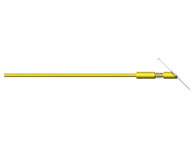
The KA Type Coaxial Insulator is a Kelvin type probe holder that features two separate probe tip holding arms protruding out from a Teflon block that is attached to a single brass shaft that inserts into a single micropositioner. The probe tip holding arms are parallel and close together so that two separate tips can both touch down in close proximity to one another and still be electrically isolated from one another. The KA probe tip holder is made with one coaxial wire that has the center conductor attached to one of the tips and the shield attached to the other tip. Note: Although either the S, the N or the E probe tip holding mechanisms will work with the KA Kelvin probe, it is suggested that the E type is used. It offers the best design for ease of adjusting the dual tips into close proximity to each other.
The KB Type Coaxial Insulator is similar to the KA type probe except that it includes two separate coaxial wires (one for each tip) and two separate BNC connectors. The center conductor from each wire is attached to one of the tip holders.
The [D] Variables Are:
- (blank) No coaxial isolation required (omit the [B] specification)
- CB Delrin insulator, 18" 50 ohm coax wire, BNC connector
- TB Teflon insulator, 18" 50 ohm coax wire, BNC connector
- GB Ceramic insulator, 18" 50 ohm coax wire, BNC connector
- KA Kelvin probe with one 18" 50 ohm coax wire, one BNC connector
- KB Kelvin probe with two 18" 50 ohm coax wires, two BNC connectors
The following are examples of probe tip holder part numbers:
U-P
The U-P part number describes a straight, 4.75" long universal probe tip holder with a spring end to secure the probe tip. The tip is secured with a spring assembly and held at a 45°angle. The probe tip holder fits into new micropositioners and all those manufactured since June, 1988. The U-P can be cut to length and bent into a particular shape if desired.
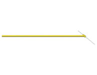
U-E-TB
The U-E-TB defines a straight, 4.75" long universal probe tip holder with the dual sockets to secure the probe tip. The tip extends out horizontally and can be bent down near the end to make a low profile shape. A Teflon insulator is installed near the end of the tip holder to isolated most of the holder from the probe tip, reducing capacitance. An 18" long, 50 Ohm coax wire is soldered on in the area where the tip inserts to provide electrical connection to the tip. The 50 Ohm wire terminates with a BNC connector. The probe tip holder fits into new micropositioners and all those manufactured since June, 1988. The U-E-TB can be cut to length and bent into a particular shape if desired.
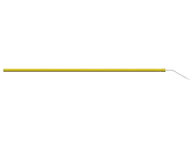
S1-S-1-CB
The S1-S-1-CB is narrower in diameter at the end where it inserts into the micropositioner, making it compatible with micropositioners manufactured prior to June 1988. The overall length is 2.25". The tip is held at a 45°angle and is secured with a small phillister head screw. A Delrin insulator is installed near the probe tip holding end to isolated most of the holder from the probe tip, reducing capacitance. An 18" long, 50 Ohm coax wire is soldered on in the area where the tip inserts, to provide electrical connection to the tip. The 50 Ohm wire terminates with a BNC connector. |


