Semiconductor Device Failure Analysis Using A Computer Aided Probing System
The tasks involved in analyzing a semiconductor device failure include finding the correct lines or nodes to probe, placing probe tips on probing targets, and often, re-locating and re-probing targets on the same unit or another unit. The use of a programmable, intra-device navigation system greatly reduces the time and effort required to perform these tasks and provides greater protection for the device under test.
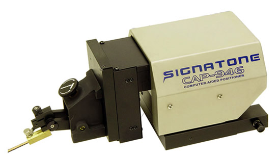
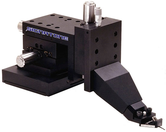
Signatone's Computer Aided Probing System consists of mechanical and electronic enhancements to either an automatic or manual probe station. The system includes a computer (PC), a proprietary Windows software program, a motorized X-Y microscope stage, a microscope with motorized focus control, Computer Aided Probes, i.e., motorized micropositioners or "CAP" probes and contact sensing hardware. A video system is also normally used. An "on-screen" video system that displays a digitized real-time image of the device-under-test on the computer monitor is another powerful option.
|
|
|
| |
|
| |
Set-up
A set-up file is made to record the device name and die size. The CAP Probing System can be used to measure the device for this purpose. The set-up file also saves the alignment data.
|
|
| |
|
| |
Alignment
An important feature of the navigational system is the ability to orient both the microscope and the CAP probes to the device in a repeatable manner. The Signatone Solutions Windows software includes a three point alignment routine that teaches both the microscope and the motorized micropositioners, the X, Y and Z plane that the device is located in. The use of this feature prior to recording locations within the device insures that recorded locations can be found again when a new device is loaded and the alignment is performed again.
|
|
| |
|
| |
Operation
Once the initial three point alignment has been performed, there are several different modes of operation. One method is to visually scan the device by driving the microscope under motorized control. Once a potential probing target is located, any of up to four CAP probes can be automatically called by selecting the "follow scope" icon. A list of the installed CAP probes is displayed.
Upon selecting the desired CAP probe, the probe tip will lift up a user defined distance, and travel automatically into the microscope's field of view. The probe tip will automatically lower again to either the actual Z plane or to the user defined "nearlanding" Z height.
The software has precision directional and speed controls for accurately positioning the probe tip into final contact. This inherent "hands-off" probing environment provides an element of solidity and control that protects the device from damage caused by an unstable hand. Systems equipped with the "on-screen" video option can take advantage of the powerful "point and shoot" feature. An optional "contact sensing" feature signals contact when the tip touches a conductive material. "Point and shoot" and "contact sensing" features are described below.
|
|
| |
|
| |
Contact Sensing
The contact sensing feature is driven by a PC peripheral card. It works in both active and passive modes. In the passive mode, the tip is slightly charged. Dissipation of the charge into a conductor signals contact. A Picoprobe power supply is also built onto the board. When used with a Picoprobe active probe arm (used to measure internal node voltages without capacitively loading the circuit), a slight change in capacitance signals contact. A message on the computer monitor and an audible "beep" signal contact to the user. The contact sensing feature also prevents the tip from lowering any further, once contact has been sensed.
|
|
| |
|
| |
Point and Shoot
The "point and shoot" command provides a very quick and easy way to direct the positioning of the microscope and the Computer Aided Probes. This feature is available on systems that are equipped with the "on-screen" video feature. A real-time video card is installed into the system controller and a CCD camera is installed onto the microscope. Clicking the video icon on the Signatone Solutions software brings the video image of the device to a window on the computer screen.
Calibrating the "point and shoot" function is done by pointing to a spot on the video screen with the mouse and clicking once. Next, move the microscope (under motor control) to another location, leaving the original spot within the field of view. Click on the same spot a second time (now that the point is at a new location on the screen). The software calculates the difference between the distance that the motors moved the microscope and the distance in pixels from the original location to the new location.
From that point on, for that particular objective, any of the Computer Aided Probes or the microscope can be moved to any point shown on the video screen by simply pointing with the mouse cross-hair to a spot on the video screen and clicking the mouse. The calibration must be done once for each objective. Even while scanning around a device using the 100X objective, a Computer Aided Probe can be called from across the device into the field of view of the microscope using the "point and shoot" feature.
|
|
| |
|
| |
Recording Points
X-Y-Z coordinate location can be recorded for either the microscope's position, or for any of up to four Computer Aided Probes by clicking on the "enter" icon. The default name assigned to a location is a consecutive number, i.e., first location is 1, second location is 2, etc. However, the locations can also be assigned labels such as "vcc", "clock1" etc., using the standard DOS file name format and the "enter label" icon.
|
|
| |
|
| |
Moving to Locations
A software button labeled "chase on" puts the system into a mode in which the microscope will always travel to X-Y locations before the Computer Aided Probes move. When probing at high magnification, this allows the user to watch the probe tip as it arrives into the field of view.
Computer Aided Probe can be driven to previously recorded location by selecting the "go label", "next" or "back" icons. The "go label" command displays a list of the recorded locations. Selecting a label can drive both the microscope and the Computer Aided Probe to the specified location. The "next" and "back" icons step the probe forwards and backwards through the points in the order in which they were recorded. Thousands of locations for any particular device can be recorded and stored on the computer's hard drive for future recall.
|
|
| |
|
| |
Other Features / Options
The microscope and the Computer Aided Probes can also be driven to coordinate locations entered from the keyboard or from a list of coordinates points that has been stored as an ASCII file. Signatone offers several prober mounted lasers that can be integrated into the navigation system to provide control through the Windows environment. The precise and programmable control of the microscope, coupled with the laser's precision cutting capability, provides a very powerful tool for local passivation removal and metal/poly trace cutting.
|
|
| |
|
| |
Summary
The Signatone Computer Aided Probing Systems provides a probing environment in which probing targets can be easily found, stored, retrieved and probed in a repeatable fashion with the aid of computerized probing hardware and Signatone's proprietary software. The benefits are:
- Savings in time spent probing
- Protection for the device being probed through the use of "hands-off" remotely controlled hardware and contact sensing
|
|
 |


